
How to install the Game Boy Color OSD Q5 IPS LCD Kit
What you will need.
Game Boy Color OSD Q5 IPS LCD KitTri-Wing / Phillips Head Game Boy ScrewdriversFlush CuttersGame Boy Color ConsoleKapton or Electrical TapeRazor Blade or Craft Knife
Not sure which screen is right for you? Click HERE for a full breakdown of the different screens available for modding.
Step one. Dissembling the GBC.
Dissemble your GBC by removing the 6 Tri-wing screws from the back of the console and remove the rear casing.
Remove the 3 Phillip’s head screws from the circuit board and detach the LCD ribbon cable by lifting up the tabs as shown below.

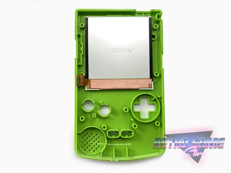
The LCD will likely be held in place with an adhesive layer, so take caution when removing both the LCD and adhesive layer from the front casing. The LCD can be set aside as it is no longer required for this installation.Step two. Trimming the shell.
WARNING: Please wear eye protection when completing this step.
It is required that you increase the viewing area & remove some inner walls to accommodate the larger screen. I recommend scoring the areas you need to remove with a craft blade and then using a pair of flush cutters to cut out them out. The IPS display needs to sit flush against the casing, so make sure the inner walls are removed completely and there are no remaining pieces that could damage the screen when the casing is tightened.

The viewable screen dimensions are 50mm x 45mm – but it’s recommended that you expand the viewing area 1-2mm larger than that so the edges are hidden beneath the screen lens bezel. If you have a 3D printer you print this template as a guide. Please refer to the images below for guidance.
Areas that require trimming are highlighted pink.
Step three. Initial screen test.
We strongly recommend testing the IPS screen and ribbon cable before adhering it to the casing.
Attach the IPS display to the OSD PCB and insert the ribbon cable into the GBC as shown below.
The connection on the IPS screen can be easily damaged so please exercise extreme caution when attaching the IPS screen connector to the PCB.

Place the GBC’s circuit board back into the rear casing and temporarily secure it with one of the Phillip’s head screws you removed earlier. Insert the batteries and switch the console on to test the screen. If the screen is working successfully you can proceed to the next step.
Step four. Installing the screen.
Remove the adhesive backing from the screen lens and adhere the lens to the casing. Do not remove the protective film from the front of the screen and try to avoid touching the inside of the screen lens as fingerprints will be difficult to remove.
Take the adhesive tape that was included in the kit and adhere it to the casing as shown below.
You can now remove the protective film from the LCD. Carefully secure the LCD to the adhesive. DO NOT FORCE THE SCREEN DOWN. Take your time and exercise extreme caution during this step. The LCD is very fragile and can bend and become damaged if you apply too much force. Once the screen is stuck to the adhesive you may not be able to make any further adjustments without risking damaging the screen so take your time when positioning the LCD.
Attach the insulating film that is included in the kit to the back of the LCD as shown below.
Step five. Soldering the wires (Optional).
This step is only required if you wish to access the on-screen OSD controls. These controls allow for some additional options such as adjusting the screen image position and customizing the colour palettes. If you do not wish to solder the wires you can still adjust the screens brightness and toggle colour palettes by using the conductive touch pads.Reattach the IPS screen ribbon cable to the PCB. Solder three wires to the pads marked ‘SEL’, ‘A’ & ‘B’ as shown below.
The PCB needs to be properly insulated. If there is any contact between the PCB and the other internal components of the GBC it could prevent the screen from functioning correctly. The kit includes an insulating film for the PCB but the adhesion is poor so I recommend using Kapton tape instead.
Solder the ‘SEL’ wire to the pad on the GBC labeled P12, the ‘A’ wire to the pad labeled P10 and the ‘B’ wire to the pad labeled P11.
Step six. Completing the installation.
The screen’s brightness level and colour palettes can be cycled by using touch sensitive pads that can be placed against the casing as shown below. The pads have an adhesive backing that can be used to secure them in place. Make sure the pads are not touching the metal shield surrounding the screen as this will effect the pads functionality. The touch pads can also be desoldered and removed if you wish to only use the on-screen controls.
Place the power switch, IR cover, buttons and button pads back into position. You can now connect the ribbon cable to the GBC circuit board and secure it into position using the 3 Phillip’s head screws you removed earlier. Be careful the ribbon cable stays in place during this step as it can easily become disconnected from the OSD PCB.Now would be a good time to test the console. Ensure the wires are positioned in a way they will not be crushed, replace the rear casing and power the console on. If everything is working successfully you can complete the mod by securing the rear casing with the 6 Tri-wing screws you removed earlier.
Step seven. Using the on-screen menu.
To access the on-screen menu, press the ‘Select’, ‘A’ & ‘B’ buttons at the same time. Once the menu is open you can press the ‘A’ & ‘B’ buttons to cycle through the menu options. Press ‘Select’ & ‘A’ to enter the selected option and press ‘Select’ & ‘B’ to leave a selected option.
Congratulations! You’ve completed the installation.